Internal Sinus Floor Elevation with Simultaneous
Internal Sinus Floor Elevation with Simultaneous
Implant Placement at Teeth #25 and #26
A Step-by-Step Communication Case
____________________________________________________________
1. Patient Information
Patient: Mr. Zhou
Sex / Age: Male, 71 years old
Date of Initial Visit: April 30, 2025
Chief Complaint: Pain and discomfort in the right upper posterior region for one week.
2. Clinical Findings & Diagnosis
A failing porcelain-fused-to-metal (PFM) splinted crown (#24-#26) was observed, with open margins and poor marginal adaptation to the underlying tooth structure. The surrounding gingiva showed mild inflammation and punctate bleeding on gentle probing. Tooth #25 was missing; tooth #26 exhibited subgingival caries extending to the level of the gingival margin and was non-responsive to thermal pulp testing. Tooth #24 displayed an old amalgam occlusal restoration and a black distal cervical caries cavity reaching deep dentin, with transient sensitivity on air-blast testing. Heavy accumulation of food debris and soft plaque was noted beneath the failing crown. Cone-beam computed tomography (CBCT) confirmed periapical pathology of tooth #26 with extension into the floor of the left maxillary sinus, presenting as a radiolucent shadow.
Pre-operative documentation
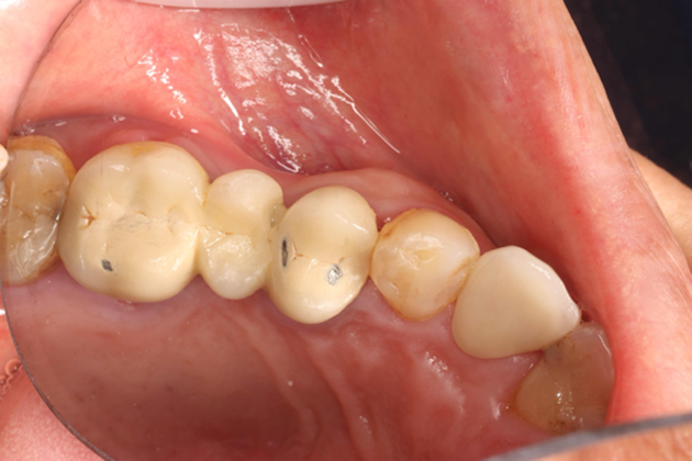
Fig. 1. Pre-operative intraoral view showing the failing PFM splinted crown (#24-#26) with open margins and associated gingival inflammation.
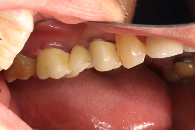
Fig. 2. Buccal view demonstrating marginal discrepancy, plaque accumulation, and localized gingivitis around the failing prosthesis.
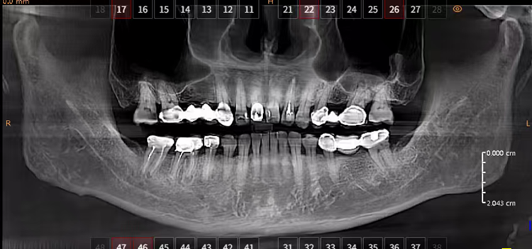
Fig. 3. Pre-operative panoramic radiograph revealing missing tooth #25, periapical lesion of tooth #26, and reduced sub-antral bone height in the #26 region.
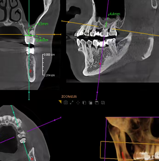
Fig. 4. CBCT cross-sectional view of the #26 site: residual sub-antral bone height of approximately 4.4–5.0 mm, insufficient for standard-length implant placement without sinus floor elevation.
3. Treatment Plan & Informed Consent
After thorough discussion of the diagnosis, prognosis, and all reasonable treatment alternatives, a phased restorative plan was agreed upon with the patient:
· Removal of the failing PFM bridge and excavation of all secondary caries.
· Tooth #24: restoration with a single full-coverage all-ceramic crown (delivered first).
· Tooth #26: extraction, followed by a three-month soft- and hard-tissue healing period.
· Stage I surgery: internal (osteotome) sinus floor elevation with simultaneous implant placement at sites #25 and #26.
· Stage II surgery after six months of osseointegration: exposure with healing-abutment placement.
· Final prosthetic rehabilitation with screw-retained porcelain-fused-to-zirconia crowns.
4. Treatment Timeline
Stage 1 — April 30, 2025: Extraction of Tooth #26
Following administration of local anesthesia (4% articaine with 1:100,000 epinephrine), tooth #26 was elevated and extracted atraumatically to preserve the buccal cortical plate and interproximal papillae. The sockets were thoroughly irrigated with sterile saline and the socket walls inspected for integrity.
Extraction of #26
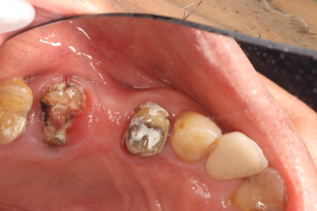
Fig. 5. Post-extraction sockets at site #26 with adjacent teeth (#24 full-coverage, #27 intact).
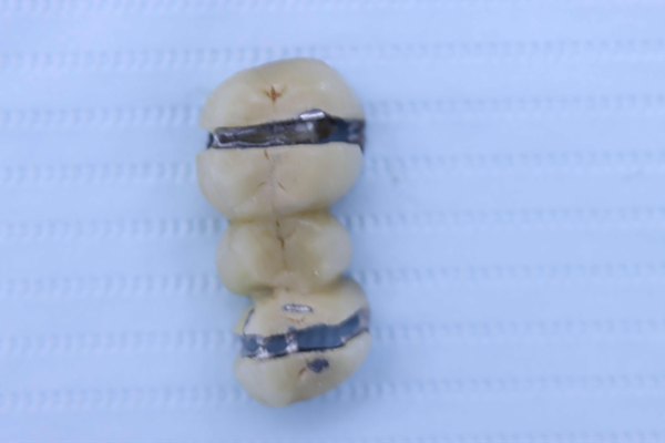
Fig. 6. Extracted PFM bridge and tooth (#24-#26) — occlusal view showing the metal substructure and bulk of food impaction beneath the crown.
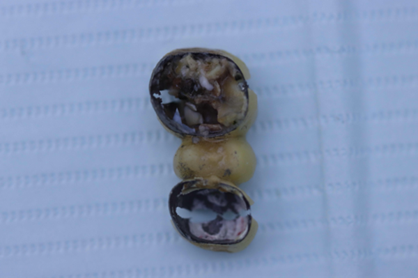
Fig. 7. Extracted specimen (basal/root surface) revealing extensive secondary caries that had developed beneath the open crown margins.
Stage 2 — May 23, 2025: Healing Check & Delivery of Crown #24
Three weeks post-extraction, the socket at #26 showed favourable soft-tissue healing with no signs of infection. Sutures were removed. The pre-fabricated all-ceramic crown for tooth #24 was tried in, occlusion verified, and cemented with resin cement.
Healing at extraction site
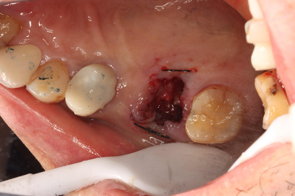
Fig. 8. Sutured extraction socket at tooth #26 immediately following the extraction procedure.
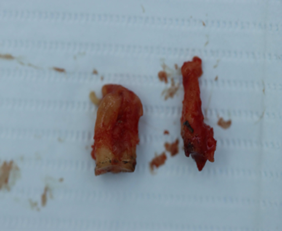
Fig. 9. Extracted root fragments retrieved during socket debridement and irrigation.
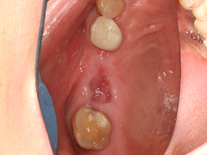
Fig. 10. Healed extraction site (#26) at three weeks: well-epithelialized socket with preserved ridge contour, ready for prosthodontic planning at #24.
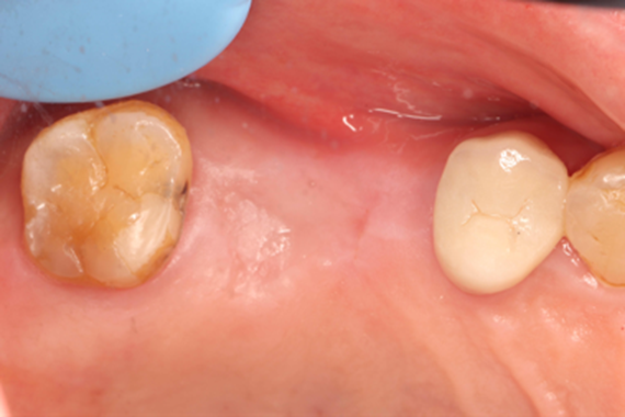
Fig. 11. Occlusal view of the healed edentulous ridge at the #26 site at three weeks post-extraction.
Stage 3 — July 22, 2025: 3-Month Re-evaluation & Pre-Surgical CBCT Planning
Three months post-extraction, the patient returned for comprehensive re-evaluation. Clinical examination showed complete soft-tissue healing at the #26 site with adequate keratinized tissue and acceptable ridge dimensions. A pre-surgical CBCT was acquired for three-dimensional implant planning, including assessment of residual sub-antral bone height and ridge width, sinus membrane integrity, and adjacent anatomical structures.
Pre-surgical CBCT analysis (3 months post-extraction)
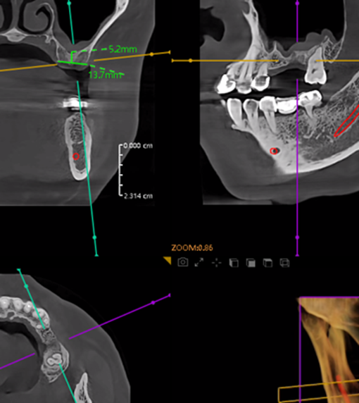
Fig. 12. CBCT cross-section at site #26: residual alveolar ridge width approximately 5.2 mm, with adequate sub-antral bone height for combined osteotome sinus lift and simultaneous implant placement.
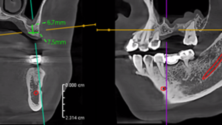
Fig. 13. CBCT cross-section at site #25: residual sub-antral bone height approximately 6.7 mm, favourable for primary implant stability.
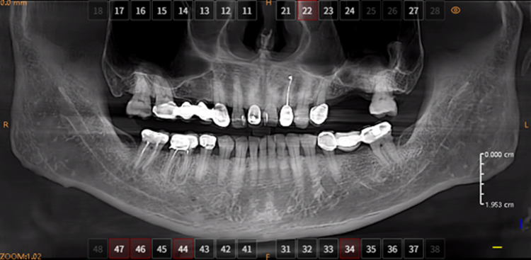
Fig. 14. Pre-surgical panoramic radiograph with proposed implant positions marked at sites #25 and #26.
Stage 4 — July 22, 2025: Stage I Surgery — Internal Sinus Lift and Implant Placement
Under local anesthesia, a full-thickness mucoperiosteal flap was elevated to expose the alveolar crest at sites #25 and #26. Sequential osteotomy preparation was performed following the surgical guide. At the #26 site, the osteotome sinus floor elevation (internal sinus lift) technique was used: a bone graft substitute (xenograft) was incrementally introduced through the osteotomy and gently apically condensed with calibrated osteotomes to elevate the Schneiderian membrane by approximately 3–4 mm, creating sufficient vertical bone height. Two dental implants were placed at sites #25 and #26 with insertion torques exceeding 35 N·cm, confirming excellent primary stability. Cover screws were inserted, and the flap was repositioned and sutured with 4-0 non-absorbable sutures (Fig. 18). Post-operative instructions and analgesics were provided.
Surgical procedure and immediate post-operative verification
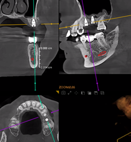
Fig. 15. Intra-operative CBCT navigation view confirming the surgical trajectory and final drill depth at sites #25 and #26.
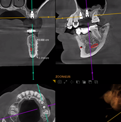
Fig. 16. Cross-sectional CBCT verification of implant positioning relative to the newly elevated sinus floor and augmented sub-antral space.
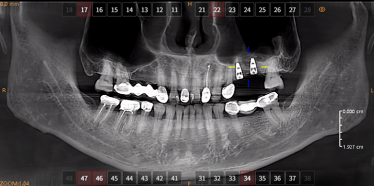
Fig. 17. Immediate post-operative panoramic radiograph demonstrating the two implants well-aligned within the augmented sinus at sites #25 and #26.
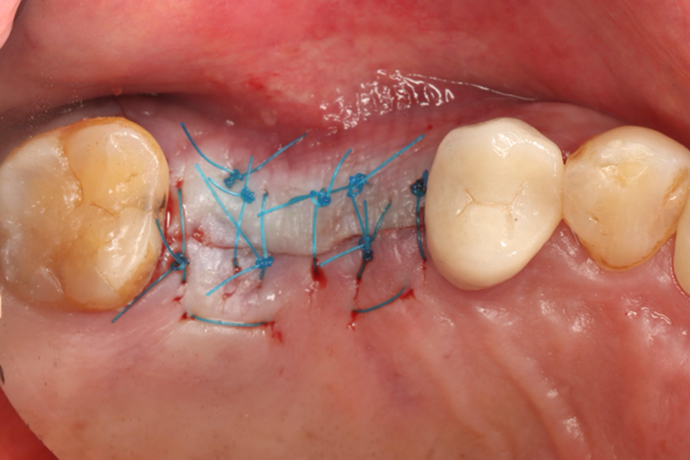
Fig. 18. Occlusal view of the tension-free sutured surgical site at the completion of Stage I implant surgery.
Stage 5 — January 21, 2026: Six-Month Follow-up & Osseointegration Assessment
At the six-month follow-up, the peri-implant soft tissues appeared healthy with no signs of inflammation, dehiscence, or membrane exposure. CBCT confirmed successful osseointegration of both implants with adequate peri-implant bone density and stable crestal bone levels, indicating that the grafted sinus had consolidated into mature, load-bearing bone.
Six-month clinical and radiographic evaluation
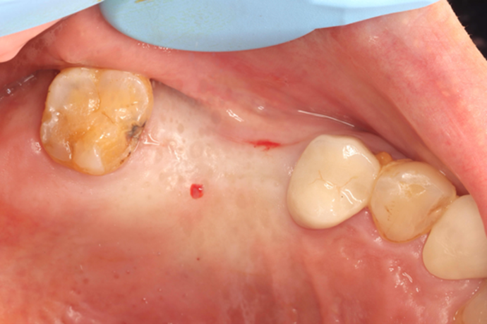
Fig. 19. Clinical photograph at six months: healthy, well-keratinized peri-implant mucosa with no inflammation or bleeding on probing.
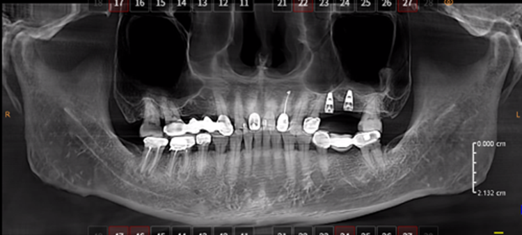
Fig. 20. Panoramic radiograph at six months showing stable crestal bone levels and integration of the grafted material in the sub-antral region.
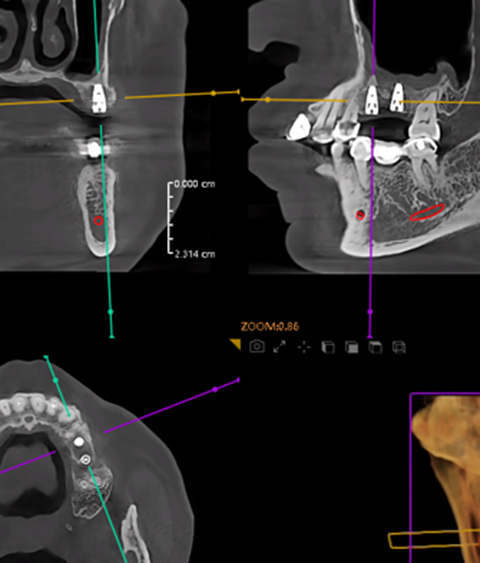
Fig. 21. CBCT cross-section at site #25: well-osseointegrated implant with intact peri-implant bone and stable buccal/lingual cortical plates.
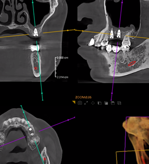
Fig. 22. CBCT cross-section at site #26: well-osseointegrated implant surrounded by mature, mineralized grafted bone in the sub-antral region.
Stage 6 — Stage II Surgery: Healing-Abutment Placement
The cover screws were exposed through a small crestal incision, removed, and replaced with appropriately sized healing abutments to contour the peri-implant soft tissues during a two-week gingival sculpting phase.
Healing abutments in situ
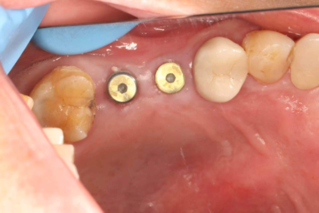
Fig. 23. Buccal view of healing abutments placed at sites #25 and #26, demonstrating well-formed peri-implant soft-tissue cuffs.
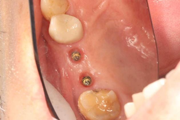
Fig. 24. Occlusal view of the two healing abutments, confirming parallel alignment and adequate emergence profile.
Stage 7 — April 22, 2026: Final Prosthetic Delivery
Open-tray impressions were taken with polyvinyl-siloxane, and screw-retained porcelain-fused-to-zirconia crowns were fabricated on custom titanium abutments. After verification of fit, occlusion, proximal contacts, and esthetics, the definitive crowns were torqued to manufacturer-recommended values, and the screw access channels were sealed with composite resin.
Definitive restorations
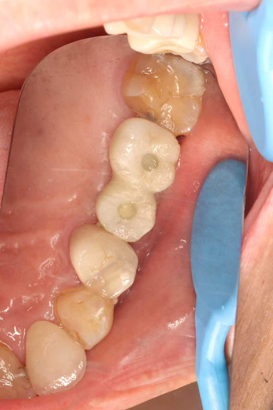
Fig. 25. Occlusal view of the final screw-retained crowns at sites #25 and #26, demonstrating harmonious occlusal anatomy, tight proximal contacts, and an optimal emergence profile.
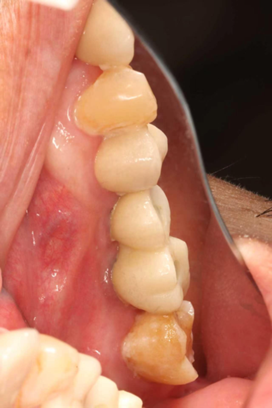
Fig. 26. Buccal view of the definitive restorations in occlusion, showing natural integration with the adjacent dentition and healthy peri-implant tissues.
Stage 8 — Final Radiographic Verification
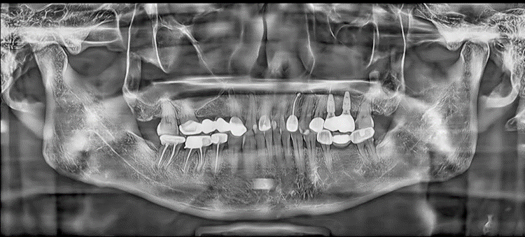
Fig. 27. Final panoramic radiograph confirming complete and passive seating of the implant abutments at sites #25 and #26, with no peri-implant radiolucency and stable crestal bone levels.
5. Before-and-After Comparison
The following comparison illustrates the transformation from the pre-operative condition—a failing PFM bridge with chronic periapical pathology and inadequate sub-antral bone—to the final implant-supported, screw-retained prosthetic rehabilitation following internal sinus floor elevation and staged implant therapy.
Treatment outcome comparison
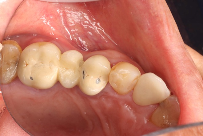
Fig. 28. Side-by-side clinical comparison: pre-operative view (failing PFM bridge and missing #25) versus the final, esthetically integrated implant-supported restorations at sites #25 and #26.
6. Clinical Summary & Key Take-aways
This case demonstrates the successful rehabilitation of a partially edentulous posterior maxilla with simultaneous internal sinus floor elevation and implant placement. Key take-aways include:
· Comprehensive pre-operative CBCT analysis is essential for evaluating residual bone dimensions, sinus membrane integrity, and adjacent anatomical structures.
· Atraumatic extraction with primary socket preservation minimizes ridge resorption and facilitates future implant placement.
· The osteotome-mediated internal sinus lift is a predictable, minimally invasive technique when the residual sub-antral bone height is ≥4–5 mm and primary implant stability can be achieved.
· Adequate healing time (six months) and radiographic verification of osseointegration should precede prosthetic loading.
· Meticulous soft-tissue management during Stage II surgery and abutment selection are critical for esthetic emergence and long-term peri-implant health.